Welcome to EEE Interview Tips

For Your Pre-Professional Preparation!

Download EEEBooks

To Download Electrical and Electronics Ebooks click the "EEE Library" menu! Enjoy!!

EEE Interview Tips

Leave Your Comments, Views And Questions.

Learn to make Electronics

Burn things out, mess things up - that's how you learn to Make Electronics! Enjoyy!!

EEE Forum

Drop your Ideas, Thoughts, Questions and Comments!

December 3, 2011

What is pitch-factor of an Alternator?

The pitch or coil span factor is defined as the ratio of actual coil voltage to the coil voltage for a full-pitch coil.

Hence, pitch factor, KP = Vector sum of induced emf per coil/ Arithmetic sum of induced emf per coil.

November 29, 2011

How to convert electrical energy to infrared energy or to microwave energy?

To convert to IR, use an IR lamp, aka heat lamp. IR is heat energy.

 To convert to microwave, you need a magnetron and a high voltage power supply, as is found in a microwave oven. 
For the reverse, it is more difficult.

November 27, 2011

Describe the Application of Synchronous Motors

Synchronous motors are usually used in large sizes because in small sizes they are costlier as compared with induction machines. The principal advantages of using synchronous machine are as follows:
–Power factor of synchronous machine can be controlled very easily by controlling the field current.

What is Synchronous Motor?

A synchronous motor is the same physical machine as a generator, except that the direction of real power flow is reversed

What are the Advantages of Parallel operation of synchronous generators?

There are several major advantages to operate generators in parallel:

  • Several generators can supply a bigger load than one machine by itself. 
  • Having many generators increases the reliability of the power system. 
  • It allows one or more generators to be removed for shutdown or preventive maintenance.

What is Synchronous Generator?

Synchronous generators or alternators are used to convert mechanical power derived from steam, gas, or hydraulic-turbine to ac electric power.

  • Synchronous generators are the primary source of electrical energy we consume today.

November 25, 2011

What is synchronous Condenser? Where and why it is used?

An overexcited synchronous motor running at no- load and used for power-factor correction is called synchronous condenser. It is also called synchronous capacitor. 

It is used in a large system where the use of static capacitor is inefficient and expensive. It is used for power-factor correction .

November 22, 2011

Why the induction motor never runs at synchronous speed?

  • If rotor & stator have same speed, no relative motion 
  • slip zero, no voltage induce in rotor 
  • current zero, torque zero 

Write down the significance of the name ‘induction’ in case of induction motor.

The supply is connected to the stator and the rotor received power by induction caused by stator rotating flux, hence the motor obtains its name –induction motor.

Why induction motor treated as a rotating transformer?

  • Transformer has two sides: primary & secondary.
  • Transformer transforms energy from primary to secondary by induction. 
  • Similarly, Induction motor has primary (stator) & secondary (rotor).
  • Voltage is induced in secondary by rotating flux of const. magnitude i.e the process of induction.
Thus induction motor treated as a rotating transformer.

October 13, 2011

What is Phase and Phase Difference?

Phase in waves is the fraction of a wave cycle which has elapsed relative to an arbitrary point.

Phase difference is the difference, expressed in electrical degrees or time, between two waves having the same frequency and referenced to the same point in time.

September 28, 2011

What are losses of Transformer? Draw an equivalent circuit of Transformer.


Losses of Transformer
The power losses in a transformer are of two types, namely;
1.         Core or Iron losses      2.         Copper losses

These  losses  appear  in  the  form  of  heat  and  produce  (i)  an  increase  in temperature and (ii) a drop in efficiency.

September 25, 2011

What is the difference between a transformer, a converter and a power supply?

Transformer

A Transformer is an electrical device by which alternating current of one voltage is changed to another voltage using coils. There are several different types, but they all basically do the same thing - change the voltage. They are usually heavy for their size due to the weight of the coils (size and weight depends on their rating).

Converter

A Converter is an electronic device that is used in some cases instead of a transformer. The converter doesn’t actually lower the voltage, but rather delays each electrical cycle making the device think it is working with the proper voltage (does not produce an output of full sine wave electricity). If you were to measure with a voltmeter the output of the converter, it would actually measure 220V (in Israel). These converters are not to be used with any electronic devices, and I personally do not recommend using them with ANY device. Although they are sold for use with hair dryers, bottle warmers, irons, etc, I’ve seen too many of these appliances ruined when used with a converter.

Power Supply

In actual fact, anything that supplies power is a Power Supply. But usually when people talk about power supplies, they are talking about a device that not only lowers the voltage, but also converts AC (alternating current) to DC (direct current). These are what you find on many small electronic devices (walkman, cordless telephones, desk clocksetc), looking like a small black box that gets plugged in the receptacle, and having a cord that plugs into whatever device you're using. If you come from the US with a device using a power supply of this type rated for 110V, simply buy the 220V equivalent here in Israel. They are relatively inexpensive and work exactly like their 110V cousin. Make sure to bring the 110V power pack with you so you can be sure of buying exactly what you need.

What is the difference between 3 phase and single-phase electricity?

I suppose the textbook definition would be something like this:

A phase is the factional part of the period of a sinusoidal wave, usually expressed in electrical degrees.

A single-phase circuit is an alternating-current using only one, sine wave type, current flowA three-phase circuit consists of three different sine wave current flows, different in phase by 120 degrees from each other.

Now let's have the more practical, "down to earth" definition - something that the average homeowner would at least have a chance of understanding:

Single phase: a circuit that consists of three wires – live, neutral, and ground (earth). The main breaker in a single phase system is a single pole breaker, resembling the others in the panel, only with a higher capacity.

Three phase: a circuit where the main breaker switches off three poles. For most home owners this is the equivalent of having 3 separate main breakers that are divided among the circuits of the home. There are 5 wires that normally constitute a three phase line, although in many homes the three phases simply supply the main and sub panels, but continue throughout most of the home as single phase lines. In most homes there are not many devices that run on three phase electricity. However, examples may include a three phase central air conditioner, a three phase oven, a 3 phase swimming pool pump, or a large 3 phase hot water boiler.

September 15, 2011

Discuss basic principles of DC generator, AC generator (Alternator) & Motor.


DC Generator Principle
An electrical generator is a machine which converts mechanical energy (or power) into electrical energy (or power).

Draw half & full wave rectifier showing input and output signals.


September 13, 2011

Define power factor. What are ways to improve power factor & describe them with necessary diagrams.

Definition of Power Factor:

The cosine of the angle between voltage and current in an AC circuit is known as power factor.


Or
The power factor of a circuit can be defined in one of the following three ways:
Power factor = cos ∅ = cosine of the angle between V and I
Power factor = R/Z=Resistance/Impedance
Power factor = (VIcos ∅)/VI=(Active Power)/(Apperant Power)

Ways to Improve Power Factor:

Power Factor is a number between 0 and 1 (frequently expressed as a percentage, e.g. 0.5 pf = 50% pf).
Normally, the power factor of the whole load on a large generating station is in the region of 0•8 to 0•9. However, sometimes it is lower and in such cases it is generally desirable to take special steps to improve the power factor. This can be achieved by the following equipment:

  1. Static capacitors.
  2. Synchronous condenser.
  3. Phase advancers.


1. Static capacitor.

The power factor can be improved by connecting capacitors in parallel with the equipment operating at lagging power factor. The capacitor (generally known as static capacitor) draws a leading current and partly or completely neutralizes the lagging reactive component of load current. This raises the power factor of the load. For three-phase loads, the capacitors can be connected in delta or star as shown in Fig. (i & ii). Static capacitors are invariably used for power factor improvement in factories.

[In industrial application it’s called Power Factor Improvement (PFI) plant or Capacitor Bank]

Advantages
(i) They have low losses.
(ii) They require little maintenance as there are no rotating parts.
(iii) They can be easily installed as they are light and require no foundation.
(iv) They can work under ordinary atmospheric conditions.

Disadvantages
(i) They have short service life ranging from 8 to 10 years.
(ii) They are easily damaged if the voltage exceeds the rated value.
(iii) Once the capacitors are damaged, their repair is uneconomical.

2. Synchronous condenser.

A synchronous motor takes a leading current when over-excited and, therefore, behaves as a capacitor. An over-excited synchronous motor running on no load is known as synchronous condenser. When such a machine is connected in parallel with the supply, it takes a leading current which partly neutralizes the lagging reactive component of the load. Thus the power factor is improved.


Fig (iii) shows the power factor improvement by synchronous condenser method. The 3∅ load takes current I_L at low lagging power factor 〖cos ∅〗_L. The synchronous condenser takes a current 〖I 〗_m which leads the voltage by an angle ∅_m. The resultant current I is the phasor sum of Im and I_L and lags behind the voltage by an angle ∅. It is clear that ∅ is less than ∅_L so that cos ∅ is greater than cos ∅_L. Thus the power factor is increased from cos ∅_L. to cos ∅. Synchronous condensers are generally used at major bulk supply substations for power factor improvement.

Advantages
By varying the field excitation, the magnitude of current drawn by the motor can be changed by any amount. This helps in achieving step less control of power factor.
The motor windings have high thermal stability to short circuit currents.
The faults can be removed easily.

Disadvantages
There are considerable losses in the motor.
The maintenance cost is high.
It produces noise.
Except in sizes above 500 kVA, the cost is greater than that of static capacitors of the same rating.
As a synchronous motor has no self-starting torque, therefore, auxiliary equipment has to be provided for this purpose.

3. Phase advancers.

Phase advancers are used to improve the power factor of induction motors. The low power factor of an induction motor is due to the fact that its stator winding draws exciting current which lags behind the supply voltage by 90o. If the exciting ampere turns can be provided from some other a.c. source, then the stator winding will be relieved of exciting current and the power factor of the motor can be improved. This job is accomplished by the phase advancer which is simply an a.c. exciter. The phase advancer is mounted on the same shaft as the main motor and is connected in the rotor circuit of the motor. It provides exciting ampere turns to the rotor circuit at slip frequency. By providing more ampere turns than required, the induction motor can be made to operate on leading power factor like an over-excited synchronous motor.

Phase advancers have two principal advantages. Firstly, as the exciting ampere turns are sup- plied at slip frequency, therefore, lagging KVAR drawn by the motor are considerably reduced. Secondly, phase advancer can be conveniently used where the use of synchronous motors is unadmissible. However, the major disadvantage of phase advancers is that they are not economical for motors below 200 H.P.
September 12, 2011

10 Interview Questions and Answers on Transformers - Part-1

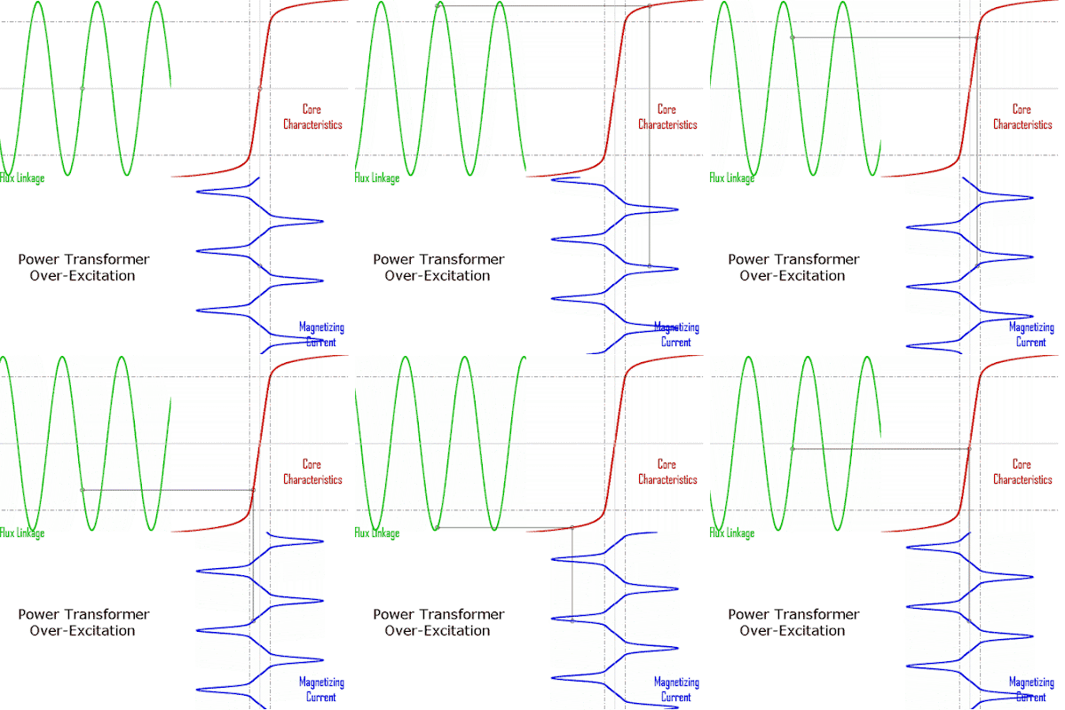
Power transformer over-excitation condition caused by decreased frequency; flux (green), iron core's magnetic characteristics (red) and magnetizing current (blue).
Figure: Power transformer over-excitation condition caused by decreased frequency; flux (green), iron core's magnetic characteristics (red) and magnetizing current (blue).


1. How is magnetic leakage reduced to a minimum in commercial transformers?

By interleaving the primary and secondary windings.

2. Mention the factors on which hysteresis loss depends?

(i) Quality and amount of iron in the core
(ii) Flux density and
(iii) Frequency.


3. How can eddy current loss be minimized?

By laminating the core.

4. In practice, what determines the thickness of the laminate or stampings?

Frequency.

5. Does the transformer draw any current when its secondary is open?

Yes, no-load primary current.

6. Why?

For supplying no-load iron and copper losses in primary.

7. Is Cu loss affected by power factor?

Yes, Cu loss varies inversely with power factor.

8. Why?

Cu loss depends on current in the primary and secondary windings. It is well-known that current required is higher when power factor is lower.

Ideal transformer and induction law.
Figure: Ideal transformer and induction law.

9. What effects are produced by change in voltage?


  1. Iron loss.........varies approximately as V2.
  2. Cu loss.........it also varies as V2 but decreases with an increase in voltage if constant kVA output is assumed.
  3. Efficiency.........for distribution transformers, efficiency at fractional loads decreases with increase in voltage while at full load or overload it increases with increase in voltage and vice versa.
  4. Regulation.........it varies as V2 but decreases with increase in voltage if constant kVA output is assumed.
  5. Heating.........for constant kVA output, iron temperatures increase whereas Cu temperatures decrease with increase in voltages and vice-versa.


10. How does change in frequency affect the operation of a given transformer?

  1. Iron loss .........increases with a decrease in frequency. A 60-Hz transformer will have nearly 11% higher losses when worked on 50Hz instead of 60 Hz. However, when a 25-Hz transformer is worked on 60 Hz, iron losses are reduced by 25%.
  2. Cu loss.........in distribution transformers, it is independent of frequency.
  3. Efficiency.........since Cu loss is unaffected by change in frequency, a given transformer efficiency is less at a lower frequency than at a higher one.
  4. Regulation.........regulation at unity power factor is not affected because IR drop is independent of frequency. Since reactive drop is affected, regulation at low power factors decreases with a decrease in frequency and vice-versa. For example, the regulation of a 25-Hz transformer when operated at 50-Hz and low power factor is much poorer.
  5. Heating.........since total loss is greater at a lower frequency, the temperature is increased with decrease in frequency.

Download this Article as PDF:
 QUESTIONS AND ANSWERS ON TRANSFORMERS

Read More: 12 Most Common Interview Questions and Answers on Transformers - Part-2

Why Transformer Rating in KVA instead of KW ?

As seen, Cu loss of a transformer depends on current and iron loss on voltage. Hence, total
transformer loss depends on volt-ampere (VA) and not on phase angle between voltage and current
i.e. it is independent of load power factor. That is why rating of transformers is in kVA and not in kW.

Another Answer:
There are 2 losses in transformer. One is copper loss which depends on current and the other is iron loss which depends on voltage. These two factors are not affected by the power factor. This is why transformers are rated in KVA and not KW. Single phase KVA = Amps x Volts/1000. Single phase KW = Amps x Volts x pf/1000. 3 phase KVA = Amps x Volts x 1.73/1000. 3 phase KW = Amps x Volts x 1.73 x pf/1000

September 10, 2011

What do you mean by real, reactive & apparent power?

a)      Real Power (P)
It is the power which is actually dissipated in the circuit resistance. Also called Active Power.


Measured in Units of Watts

b)     Reactive Power (Q)
It is the power developed in the inductive reactance of the circuit.

Related Posts Plugin for WordPress, Blogger...