Welcome to EEE Interview Tips

For Your Pre-Professional Preparation!

Download EEEBooks

To Download Electrical and Electronics Ebooks click the "EEE Library" menu! Enjoy!!

EEE Interview Tips

Leave Your Comments, Views And Questions.

Learn to make Electronics

Burn things out, mess things up - that's how you learn to Make Electronics! Enjoyy!!

EEE Forum

Drop your Ideas, Thoughts, Questions and Comments!

Showing posts with label Transmission and Distribution. Show all posts

February 22, 2017

What will happen when power factor is leading in the distribution of power?

If there is a high power factor, i.e if the power factor is close to one:

  1. Losses in the form of heat will be reduced;
  2. The cable becomes less bulky and easier to carry, and very cheap to afford, &
  3. It also reduces over heating of transformers.

January 26, 2017

Describe the types of Insulators used in Transmission and Distribution .

Insulator:

An electrical insulator is a material whose internal electric charges do not flow freely, and therefore make it nearly impossible to conduct an electric current under the influence of an electric field. This contrasts with other materials, semiconductors and conductors, which conduct electric current more easily. The property that distinguishes an insulator is its resistivity; insulators have higher resistivity than semiconductors or conductors.

Insulators are used in electrical equipment to support and separate electrical conductors without allowing current through themselves. An insulating material used in bulk to wrap electrical cables or other equipment is called insulation. The term insulator is also used more specifically to refer to insulating supports used to attach electric power distribution or transmission lines to utility poles and transmission towers. They support the weight of the suspended wires without allowing the current to flow through the tower to ground.

Types of insulators:

There are so many insulators which are recently used but these are most preferable insulators used in transmission lines . These are the common classes of insulator:

A.   Pin Type Insulator

As its name indicates, the pin type insulator is mounted on a pin which is fixed on the pole or tower. The insulator has a groove where the conductor lies, which secures the conductor to the insulator. The conductor placed on the top of the pin insulator is at live potential, whereas the bottom of the pin is at contact with the supporting structure which is usually at earth potential. This type of insulator is used for low and medium voltage distribution lines up to 33 kV. In distribution systems up to 11 kV, a one part type insulator is generally used, where whole pin insulator is one piece of properly shaped porcelain or glass.  It is important to know that pin insulators cannot be fixed one above the other for higher voltage applications.
Figure 1- Pin Type Insulator on distribution pole.

B. Post insulator

A type of insulator in the 1930s that is more compact than traditional pin-type insulators and which has rapidly replaced many pin-type insulators on lines up to 69kV and in some configurations, can be made for operation at up to 115kV.
Figure 2- Porcelain line post insulators.
This insulator can be used for both indoor and outdoor applications. The conductor contact is on both top and bottom. There are two main types: pedestal post insulator and solid core cylindrical post insulator.


C. Suspension Insulator

The suspension type insulator is utilized for high voltage transmission lines (greater than 33 kV), where the line is located bellow the point of support. Multiple insulators are connected in series, each of which is called a disc. The number of disc units used depends on the voltage. Its main advantages are simplicity in design, high mechanical strength, the ability to change individual discs in case of puncture, and the transmission line does not fall if porcelain breaks accidentally.
Figure 3- Pin and cap insulator in suspension configuration.

D.  Strain (Tension) Insulator

A strain insulator is an electrical insulator that is designed to work in mechanical tension (strain), to withstand the pull of a suspended electrical wire or cable. Therefore, they should be able to withstand very high amounts of mechanical tension. They are usually used at line terminal and at dead end. When the tension load in lines is exceedingly high, such as at long river spans, two or more strings are used in parallel.
Figure 4 - Strain Insulator.
In order to support this lateral load, strain insulators are used. For low voltage lines (less than 11 kV), shackle insulators are used as strain insulators. However, for high voltage transmission lines, strings of cap-and-pin (disc) insulators are used, attached to the crossarm in a horizontal direction.


E. Shackle insulator

In early days, the shackle insulators, also known as spool insulators,  were used as strain insulators. But now a day, they are frequently used for low voltage distribution lines. Such insulators can be used either in a horizontal position or in a vertical position. They can be directly fixed to the pole with a bolt or to the cross arm.
Figure 5- Shackle Insulator.

Shackle Insulators are used in low voltage distribution systems. Usually, they are used at the end of distribution lines or at sharp turns where there is excessive tensile load on the lines.

F.  Bushings

A bushing is an insulating structure, including a through conductor or providing a central passage for such conductor, with provision for mounting a barrier, conducting or otherwise, for the purpose of insulating the conductor from the barrier and of an electrical current from one side of the barrier to the other.
Figure 6- Bushings.

Bushings have many types, including: liquid-filled bushing, liquid-insulated bushing, gas-filled bushing, gas-insulated bushing, oil-impregnated paper bushing, and others.

G. Long Rod  Insulator

Long rod insulator are similar to solid core cylindrical insulator except that the top and bottom fittings are of pin and cap type. Long rod insulators provide an alternative to cap and pin insulators but with longer unit length. Similar to the Pin and cap insulator, it can be used in both suspension and tension (strain) configurations.  Long rod insulators are high performance insulators. According to Elsewedy Electric, long rod insulators are “absolutely puncture-proof” and have “excellent anti-pollution performance”.
Figure 8- Long rod type insulator.

H. Cap and Pin Insulators

Cap and pin insulators of porcelain or glass construction are used for applications above 33 kV, either in suspension or tension (strain) configuration. Any insulator length can be achieved by arranging a number of single disk units in a string.


I. Line post insulator

J. Station post insulator

K. Cut-out


Download this Article as PDF:
 describe-types-of-insulators-used-in

January 25, 2017

Draw the Basic structure of an electric power system.


Basic structure of an electric power system in North America.
Figure: Basic structure of an electric power system in North America.

Names of Parts on Electric Pole.


Figure: Names of parts on electric pole.


January 15, 2017

What is RMU (Ring Main Unit) and Its Use in Electrical Power Distribution System?

Ring Main Unit (RMU) is a 11 KV or 33 KV HT panel having 3 nos. of switches (Circuit Breakers or Isolators or LBS) that are 2 for incoming one for outgoing. It enables consumer use 2 sources of HT power in at the same metering point. It is a totally sealed, gas-insulated compact switchgear unit.

RMU is to be used two incoming with mechanical or electrical interlock and one out going  to the load generally but some times one incoming and two outgoings medium voltage supplies. In engineering distribution this is called flexible power supply. Now a day SF6 (Sulfer Hexa-Floride) circuit breakers going to be used. These are maintenance free breakers. 


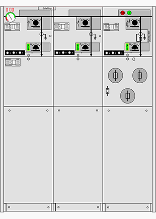
Figure 1 – Outlook of a typical three-feeder 24 kV RMU unit

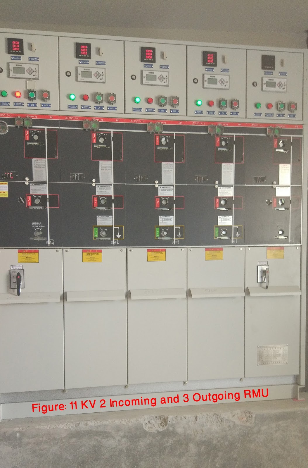
Figure 2- 11 KV 2 Incoming and 3 Outgoing RMU at Bangladesh Film Archive.

Ring Main Unit is used in a secondary distribution system. It is basically used for an uninterrupted power supply. Alongside, it also protects your secondary side transformer from the occasional transient currents. 

September 15, 2016

What are the various kind of cables used for transmission?

Cables, which are used for transmitting power, can be categorized in three forms:

  • Low-tension cables, which can transmit voltage upto 1000 volts.
  • High-tension cables can transmit voltage upto 23000 volts.
  • Super tension cables can transmit voltage 66 kV to 132 kV.

September 12, 2016

Discuss about different types of Transformers and their Applications.

Transformer:


A transformer is an electrical device that transfers electrical energy between two or more circuits through electromagnetic induction. Electromagnetic induction produces an electromotive force across a conductor which is exposed to time varying magnetic fields. Commonly, transformers are used to increase or decrease the voltages of alternating current in electric power applications.


Photo: Dry type Transformer

Types of Transformers:

1.        Power transformers

a)         Laminated core transformer
b)         Toroidal transformer
c)         Autotransformer
d)         Variable autotransformer
e)         Induction regulator transformer
f)          Polyphase transformer
g)         Grounding transformer
h)         Leakage or stray field transformers
i)          Resonant transformer
j)          Constant voltage transformer
k)         Ferrite core transformer
l)          Planar transformer
m)        Oil cooled transformer
n)         Cast resin transformer
o)         Isolating transformer

2.     Instrument transformer

a)         Current transformer
b)         Voltage transformer or potential transformer
c)         Combined instrument transformer

3.      Pulse transformer

4.      RF transformer

a)         Air-core transformer
b)         Ferrite-core transformer
c)         Transmission-line transformer
d)         Balun transformer

5.     Audio transformer

a)         Loudspeaker transformer
b)         Output transformer
c)         Small signal transformer
d)         Interstage and coupling transformers

6.     Other types

a)         Hedgehog
b)         Variometer and variocoupler
c)         Rotary transformer


Overview and Applications of Transformers:

1. Auto-transformer

An auto-transformer has only a single winding with two end terminals, plus a third of an intermediate tap point. The primary voltage is applied across two of the terminals, and the secondary voltage taken from one of these and the third terminal. The primary and secondary circuits therefore have a number of windings turns in common. An adjustable auto-transformer is made by the secondary connection through a sliding brush, giving a variable turns ratio.
Figure: Single-phase tapped autotransformer with output voltage range of 40%–115% of input

Applications: 

  • Large three-phase autotransformers are used in electric power distribution systems, for example, to interconnect 33 kV and 66 kV sub-transmission networks.

2. Polyphase transformers

For three-phase power, three separate single-phase transformers can be used, or all three phases can be connected to a single polyphase transformer. In this case, the magnetic circuits are connected together, the core, thus containing a three-phase flow of flux. The three primary windings are connected together and the three secondary windings are connected together. The most common connections are Y-∆, ∆-Y, ∆-∆ and Y-Y. If a winding is connected to earth (grounded), the earth connection point is usually at the center point of a Y winding.

Applications:

  • For higher- power applications, poly-phase transformers are commonly used. 


3. Leakage transformers

A leakage transformer, also called a stray-field transformer, has a significantly higher leakage inductance than other transformers, sometimes increased by a magnetic bypass or shunt in its core between primary and secondary, which is sometimes adjusted with a set screw. This provides a transformer with an inherent current limitation due to the loose coupling between its primary and the secondary windings. The output and input currents are low enough to prevent thermal overload under all load conditions – even if the secondary is shorted. 
Figure: Leakage Transformer or Stray field Transformer.

Applications: 

  • Leakage transformers are used for arc welding and high voltage discharge lamps. 
  • Other applications are short-circuit-proof extra-low voltage transformers for toys or doorbell installations.


4. Resonant transformers

A resonant transformer is a kind of the leakage transformer. It uses the leakage inductance of its secondary windings in combination with external capacitors, to create one or more resonant circuits. Resonant transformers such as the Tesla coil can generate very high voltages, and are able to provide much higher current than electrostatic high-voltage generation machines such as the Van de Graaff generator. 

Applications: 

  • Intermediate frequency (IF) transformer in superheterodyne radio receiver
  • Tank transformers in radio transmitters
  • Tesla coil
  • Oudin coil (or Oudin resonator; named after its inventor Paul Oudin)
  • D'Arsonval apparatus
  • Ignition coil or induction coil used in the ignition system of a petrol engine
  • Electrical breakdown and insulation testing of high voltage equipment and cables. In the latter case, the transformer's secondary is resonated with the cable's capacitance.

5. Instrument transformers

A current transformer is a measurement device designed to provide a current in its secondary coil proportional to the current flowing in its primary. Current transformers are commonly used in metering and protective relaying, where they facilitate the safe measurement of large currents. The current transformer isolates measurement and control circuitry from the high voltages typically present on the circuit being measured. Voltage transformers (VTs)--also referred to as potential transformers (PTs)--are used for metering and protection in high-voltage circuits. They are designed to present negligible load to the supply being measured and to have a precise voltage ratio to accurately step down high voltages so that metering and protective relay equipment can be operated at a lower potential.


Figure: Current transformers used in metering equipment for three-phase 400 ampere electricity supply

Applications: 

  • Used as a portable current measuring instrument.
  • Measurement of high voltages is possible by the potential transformers.


6. Zigzag transformer

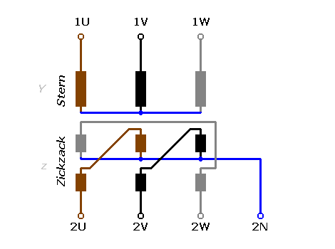
A zigzag transformer is a special purpose transformer. It has primary windings but no secondary winding. Its applications are for the creation of a missing neutral connection from an ungrounded 3-phase system to permit the grounding of that neutral to an earth reference point and also harmonic mitigation, as it can suppress triplet (3rd, 9th, 15th, 21st, etc.) harmonic currents, to supply 3-phase power as an autotransformer (serving as the primary and secondary with no isolated circuits)  and to supply non-standard, phase-shifted, 3-phase power.


Figure: Zigzag transformer

Applications: 

  • One application is to derive an earth reference point for an ungrounded electrical system. 
  • Another is to control harmonic currents.

7. Pulse transformers

A pulse transformer is a transformer that is optimized for transmitting rectangular electrical pulses (that is, pulses with fast rise and fall times and constant amplitude). 


Figure: Bothhand TS6121A pulse transformer

Applications:

  • Small versions called signal types are used in digital logic and telecommunications circuits, often for matching logic drivers to transmission lines. 
  • Medium-sized power versions are used in power-control circuits such as camera flash controllers. 
  • Larger power versions are used in the electrical power distribution industry to interface low-voltage control circuitry to the high-voltage gates of power semiconductors. 
  • Special high voltage pulse transformers are also used to generate high power pulses for radar, particle accelerators, or other high energy pulsed power applications.

8. Audio transformer

Audio transformers or Audio Frequency (AF) Transformers are those specifically designed for use in audio circuits to carry audio signal. They can be used to block radio frequency interference or the DC component of an audio signal, to split or combine audio signals, or to provide impedance matching between high and low impedance circuits, such as between a high impedance tube (valve) amplifier output and a low impedance loudspeaker, or between a high impedance instrument output and the low impedance input of a mixing console. Audio transformers that operate with loudspeaker voltages and current are larger than those that operate at microphone or line level, which carry much less power.


Figure: Audio Frequency (AF) Transformers

Application: 

  • Audio transformers are used in car radios and broadcast equipment, and in sound reinforcement applications to steps up the output of the system's amplifier.


9. Isolation transformers 

An isolation transformer is a device that transfers energy from the alternating current (AC) supply to an electrical or electronic load.  It isolates the windings to prevent transmitting certain types of harmonics. 


Figure: A 230V isolation transformer.

Applications: 

  • It is used as a power supply for medical equipment, when it is necessary to prevent any leakage from the AC power system into devices connected to a patient.
  • Some small transformers are used for isolation in pulse circuits.
  • In electronics testing and servicing an isolation transformer is a 1:1 (under load) power transformer used for safety.
  • Supplying power to ships.

10. Buck boost transformers

A Buck boost transformer is a type of transformer used to make adjustments to the voltage applied to alternating current equipment. Buck boost transformers make small adjustments to the incoming voltage. One major advantages of Buck boost transformers are their low cost, compact size and light weight. 
Figure: Typical multi-tap buck–boost transformer.

Applications:

  • Buck boost transformers can be used to power low voltage circuits including control, lighting circuits, or applications that require 12, 16, 24, 32 or 48 volts, consistent with the design's secondaries.
  • They are often used to change voltage from 208v to 240v for lighting applications. 

11. Pad mounted transformers 

A padmount or pad-mounted transformer is a ground mounted electric power distribution transformer in a locked steel cabinet mounted on a concrete pad. Since all energized connection points are securely enclosed in a grounded metal housing, a padmount transformer can be installed in places that do not have room for a fenced enclosure. Padmount transformers are used with underground electric power distribution lines at service drops, to step down the primary voltage on the line to the lower secondary voltage supplied to utility customers. A single transformer may serve one large building, or many homes. Pad Mounted Transformers are usually single phase or three phase and is used where safety is a main concern.


Figure: Large pad-mount transformers supplying power to a computer data center. No live wires are exposed.

Applications:

  • Typical Application is restaurant, commercial building, shopping mall, institutional. 


12. Pole mounted transformers 

Outside a typical house one can see one of these devices mounted on the top of an electrical pole.
Figure: Pole mounted distribution transformer.

Applications:

  • Pole Mounted Transformers are used for distribution in areas with overhead primary lines. 


13. Oil filled transformers 

Oil-filled transformers are transformers that use insulating oil as insulating materials.  The oil helps cool the transformer. Because it also provides part of the electrical insulation between internal live parts, transformer oil must remain stable at high temperatures over an extended period.

Applications: 

  • Oil filled transformers are used in power distribution or electrical substations.


14. Rotary transformers

A rotary (rotatory) transformer is a specialized transformer used to couple electrical signals between two parts that rotate in relation to each other. They may be either cylindrical or 'pancake' shaped.


Figure: Cross-section diagram of a simple rotary transformer.

Applications: 

  • Rotary transformers are most commonly used in videocassette recorders. 
  • Another use is to transmit the signals from rotary torque sensors installed on electric motors, to allow electronic control of motor speed and torque using feedback.

15. Dry type transformers 

Dry type transformers require minimum maintenance to provide many years of reliable trouble free service. Unlike liquid fill transformers which are cooled with oil or fire resistant liquid dielectric, dry type units utilize only environmentally safe, CSA and UL recognized high temperature insulation systems. Dry type transformers provide a safe and reliable power source which does not require fire proof vaults, catch basins or the venting of toxic gasses. These important safety factors allow the installation of dry type transformers inside buildings close to the load, which improves overall system regulation and reduces costly secondary line losses. 

Dry type transformers are a rather mature product and technology, but of all the components in a power system, a transformer replacement can be a physically challenging event, extended delivery of a replacement or repair unit and expensive transportation costs. These are transformers whose core and coils are not immersed in insulating oil. 

“Dry type” simply means it is cooled by normal air ventilation. The dry type transformer does not require a liquid such as oil or silicone or any other liquid to cool the electrical core and coils

Applications:

  • Fire-resistant dry type or "cast resin" transformers are well suited for installation in high rise buildingshospitalsunderground tunnelsschoolsteel factories, chemical plants and places where fire safety is a great concern. Hazard free to the environment, dry type transformers have over the years proven to be highly reliable. 

Download this Article as PDF:
 Different Types Of Transformers And Their Applications

Related Posts Plugin for WordPress, Blogger...