An electrical insulator is a material whose internal electric charges do not flow freely, and therefore make it nearly impossible to conduct an electric current under the influence of an electric field. This contrasts with other materials, semiconductors and conductors, which conduct electric current more easily. The property that distinguishes an insulator is its resistivity; insulators have higher resistivity than semiconductors or conductors.
Insulators are used in electrical equipment to support and separate electrical conductors without allowing current through themselves. An insulating material used in bulk to wrap electrical cables or other equipment is called insulation. The term insulator is also used more specifically to refer to insulating supports used to attach electric power distribution or transmission lines to utility poles and transmission towers. They support the weight of the suspended wires without allowing the current to flow through the tower to ground.
Types of insulators:
There are so many insulators which are recently used but these are most preferable insulators used in transmission lines . These are the common classes of insulator:
A. Pin Type Insulator
As its name indicates, the pin type insulator is mounted on a pin which is fixed on the pole or tower. The insulator has a groove where the conductor lies, which secures the conductor to the insulator. The conductor placed on the top of the pin insulator is at live potential, whereas the bottom of the pin is at contact with the supporting structure which is usually at earth potential. This type of insulator is used for low and medium voltage distribution lines up to 33 kV. In distribution systems up to 11 kV, a one part type insulator is generally used, where whole pin insulator is one piece of properly shaped porcelain or glass. It is important to know that pin insulators cannot be fixed one above the other for higher voltage applications.
Figure 1- Pin Type Insulator on distribution pole.
B. Post insulator
A type of insulator in the 1930s that is more compact than traditional pin-type insulators and which has rapidly replaced many pin-type insulators on lines up to 69kV and in some configurations, can be made for operation at up to 115kV.
Figure 2- Porcelain line post insulators.
This insulator can be used for both indoor and outdoor applications. The conductor contact is on both top and bottom. There are two main types: pedestal post insulator and solid core cylindrical post insulator.
C. Suspension Insulator
The suspension type insulator is utilized for high voltage transmission lines (greater than 33 kV), where the line is located bellow the point of support. Multiple insulators are connected in series, each of which is called a disc. The number of disc units used depends on the voltage. Its main advantages are simplicity in design, high mechanical strength, the ability to change individual discs in case of puncture, and the transmission line does not fall if porcelain breaks accidentally.
Figure 3- Pin and cap insulator in suspension configuration.
D. Strain (Tension) Insulator
A strain insulator is an electrical insulator that is designed to work in mechanical tension (strain), to withstand the pull of a suspended electrical wire or cable. Therefore, they should be able to withstand very high amounts of mechanical tension. They are usually used at line terminal and at dead end. When the tension load in lines is exceedingly high, such as at long river spans, two or more strings are used in parallel.
Figure 4 - Strain Insulator.
In order to support this lateral load, strain insulators are used. For low voltage lines (less than 11 kV), shackle insulators are used as strain insulators. However, for high voltage transmission lines, strings of cap-and-pin (disc) insulators are used, attached to the crossarm in a horizontal direction.
E. Shackle insulator
In early days, the shackle insulators, also known as spool insulators, were used as strain insulators. But now a day, they are frequently used for low voltage distribution lines. Such insulators can be used either in a horizontal position or in a vertical position. They can be directly fixed to the pole with a bolt or to the cross arm.
Figure 5- Shackle Insulator.
Shackle Insulators are used in low voltage distribution systems. Usually, they are used at the end of distribution lines or at sharp turns where there is excessive tensile load on the lines.
F. Bushings
A bushing is an insulating structure, including a through conductor or providing a central passage for such conductor, with provision for mounting a barrier, conducting or otherwise, for the purpose of insulating the conductor from the barrier and of an electrical current from one side of the barrier to the other.
Figure 6- Bushings.
Bushings have many types, including: liquid-filled bushing, liquid-insulated bushing, gas-filled bushing, gas-insulated bushing, oil-impregnated paper bushing, and others.
G. Long Rod Insulator
Long rod insulatorare similar to solid core cylindrical insulator except that the top and bottom fittings are of pin and cap type. Long rod insulators provide an alternative to cap and pin insulators but with longer unit length. Similar to the Pin and cap insulator, it can be used in both suspension and tension (strain) configurations. Long rod insulators are high performance insulators. According to Elsewedy Electric, long rod insulators are “absolutely puncture-proof” and have “excellent anti-pollution performance”.
Figure 8- Long rod type insulator.
H. Cap and Pin Insulators
Cap and pin insulators of porcelain or glass construction are used for applications above 33 kV, either in suspension or tension (strain) configuration. Any insulator length can be achieved by arranging a number of single disk units in a string.
The embedding of microprocessor chip technology and power electronic devices in the design of intelligent AC voltage stabilizers (or automatic voltage regulators (AVR)) led to produce high-quality, stable electric power supply in the event of significant and continuous deviation of mains voltage.
As advancement to the conventional relay type voltage stabilizers, modern innovative stabilizers use high performance digital control circuits and solid state control circuitry that eliminates potentiometer adjustments and allows the user to set voltage requirements through a keypad, with output start and stop facility.
Figure 1- Voltage Stabilizer
This also led to make the trip timing or responsiveness of the stabilizers to a very less rate, typically less than a few milliseconds, in addition this can be adjusted with variable setting. Nowadays, stabilizers became an optimized power solution to many electronic appliances that are sensitive to voltage fluctuations and they have found working with many devices such as CNC machines, air conditioners, television sets, medical equipment, computers, telecommunication equipments, and so on.
What is a Voltage Stabilizer?
It is an electrical appliance which is designed to deliver a constant voltage to a load at its output terminals regardless of the changes in the input or incoming supply voltage. It protects the equipment or machine against over voltage, under voltage, and other voltage surges.
It is also called as automatic voltage regulator (AVR). Voltage stabilizers are preferred for costly and precious electrical equipments to protect them from harmful low/high voltage fluctuations. Some of these equipments are air conditioners, offset printing machines, laboratory equipments, industrial machines, and medical apparatus.
Voltage stabilizers regulate the fluctuating input voltage before it could be fed to the load (or equipment which is sensitive to voltage variations). The output voltage from the stabilizer will stay in the range of 220V or 230V in case of single phase supply and 380V or 400V in case of three phase supply, within given fluctuating range of input voltage. This regulation is carried by buck and boost operations performed by internal circuitry.
There are huge varieties of automatic voltage regulators are available in today’s market. These can be single or three-phase units as required by the type of application and capacity (KVA) needed. Three-phase stabilizers come in two versions as balanced load models and unbalanced load models.
These are available either as dedicated units for appliances or as a big stabilizer unit for whole appliances in a particular place, say whole house. In addition, these can be either analog or digital type of stabilizer units.
The common types of voltage stabilizers include manual operated or switchable stabilizers, automatic relay type stabilizers, solid state or static stabilizers, and servo controlled stabilizers. In addition to the stabilizing function, most stabilizers come with additional features such as input/output low voltage cutoff, input/output high voltage cutoff, overload cutoff, output start and stop facility, manual/auto start, voltage cutoff display, zero voltage switching, etc.
Why Voltage Stabilizers Are Needed?
Generally, each and every electrical equipment or device is designed for a wide range of input voltage. Depending on the sensitivity, the working range of the equipments are limited to a specific values, for instance, some equipments can tolerate ± 10 percent of the rated voltage while others ± 5 percent or less.
The voltage fluctuations (rise or dip of the magnitude of rated voltage) are quite common in many areas, especially at terminated lines. The most common reasons for voltage fluctuations are lighting, electrical faults, faulty wiring and periodic turning off the device. These fluctuations create mishap to the electrical equipments or appliances.
Long time over voltage will result:
Permanent damage to the equipment
Insulation damage to the windings
Unwanted interruption in the load
Increased losses in cables and associated equipments
De-rating life of the appliance
Long time under voltage will result:
Malfunctioning of the equipment
Longer working periods (as in case of resistive heaters)
Reduced performance of the equipment
Drawing large currents which further lead to overheating
Computational errors
Reduced speed of motors
So the voltage stability and accuracy decide the correct operation of the equipment. Voltage stabilizers therefore ensure that the voltage fluctuations at the incoming power supply does not affect the load or electrical appliance.
How Voltage Stabilizer Works?
Basic Principle of voltage stabilizer to Perform Buck and Boost Operations
In a voltage stabilizer, voltage correction from over and under voltage conditions is performed through two essential operations, namely boost and buck operations. These operations can be carried manually by switches or automatically through electronic circuitry. During under voltage condition, boost operation increases the voltage to a rated level while buck operation reduces the voltage level during over voltage condition.
The concept of stabilization involves in adding or subtracting the voltage to and from the mains supply. For performing such task stabilizer uses a transformer which is connected in different configurations with switching relays. Some stabilizers use a transformer with taps on winding to provide different voltage corrections while servo stabilizers use an auto transformer to have wide range of correction.
To understand this concept, let us consider simple step down transformer of 230/12V rating and its connection with these operations are given below.
Figure 2- Boost Operation of Stabilizer
The figure above illustrates the boosting configuration in which the polarity of the secondary winding is oriented in such a way that its voltage is directly added to the primary voltage. Therefore, in case of under voltage condition, transformer (whether it can be tap changing or autotransformer) is switched by the relays or solid state switches such that additional volts are appended to the input voltage.
Figure 3- Buck operation of Voltge Stabilizer
In the figure above, transformer is connected in bucking configuration, wherein the polarity of secondary coil is oriented in such a way that its voltage subtracts from the primary voltage. The switching circuit shifts the connection to the load to this configuration during over voltage condition.
Figure 4- Two-stage voltage stabilizer. Buck and Boost Operations of Stabilizer
The figure above shows two stage voltage stabilizer which uses two relays to provide constant AC supply to the load during overvoltage and under voltage conditions. By switching the relays, buck and boost operations for two specific voltage fluctuations (one is under voltage, for instance, say 195V and another for overvoltage, say 245V) can be performed.
In case of tapping transformer type stabilizers, different taps are switched based on the required amount of boost or buck voltages. But, in case of auto transformer type stabilizers, motors (servo motor) are used along with sliding contact to obtain boost or buck voltages from the auto transformer as it contains only one winding.
Types of Voltage Stabilizers
Voltage stabilizers have become integral part of many electrical appliances of home, industries and commercial systems. Earlier, manually operated or switchable voltage stabilizers were used to boost or buck incoming voltage in order to give an output voltage within a desired range. Such stabilizers are built with electro-mechanical relays as switching devices.
Later, additional electronic circuitry automates the process of stabilization and gave birth to tap changer automatic voltage regulators. Another popular type of voltage stabilizer is servo stabilizer in which voltage correction is carried continuously without any switch. Let us discuss three main types of voltage stabilizers.
Relay Type Voltage Stabilizers
In this type of voltage stabilizers, voltage regulation is accomplished by switching the relays so as to connect one of a number of tappings of the transformer to the load (as in the manner discussed above) whether it is for boosting or bucking operation. The figure below illustrates the internal circuitry of relay type stabilizer.
It has electronic circuit and set of relays besides the transformer (which can be toroidal or iron core transformer with tappings provided on its secondary). The electronic circuit comprises rectifier circuit, operational amplifier, microcontroller unit, and other tiny components.
Figure 5- Relay-type voltage stabilizer
The electronic circuit compares the output voltage with a reference value provided by built-in reference voltage source. Whenever the voltage rises or falls beyond reference value, the control circuit switches the corresponding relay to connect a desired tapping to the output.
These stabilizers usually change the voltage for input voltage variations of ±15 percent to ±6 percent with output voltage accuracy of ±5 to ±10 percent. This type of stabilizers is most popularly used for low rating appliances in residential, commercial and industrial applications as they are of low weight and low cost. However, these are suffering with several limitations such as slow voltage correction speed, less durability, less reliability, interruption to power path during regulation, and unable to withstand high voltage surges.
Servo Controlled Voltage Stabilizers
These are simply termed as servo stabilizers (work on servomechanism which also known as negative feedback) and the name suggests it uses a servo motor to enable the voltage correction. These are mainly used for high output voltage accuracy, typically ±1 percent with input voltage changes up to ± 50 percent. The figure below shows the internal circuit of a servo stabilizer which incorporates servo motor, auto transformer, buck boost transformer, motor driver and control circuitry as essential components.
Figure 6- Servo voltage stabilizer
In this stabilizer, one end of buck boost transformer primary is connected to the fixed tap of the auto transformer, while other end is connected to the moving arm that is controlled by the servo motor. Secondary of the buck boost transformer is connected in series with incoming supply which is nothing but stabilizer output.
Figure 7- Servo motor working
Electronic control circuit detects the voltage dip and voltage rise by comparing the input with built-in reference voltage source. When the circuit finds the error, it operates the motor that in turn moves the arm on the autotransformer. This could feed the primary of buck boost transformer such that a voltage across the secondary should be the desired voltage output. Most servo stabilizers use embedded microcontroller or processor for the control circuitry to achieve intelligent control.
These stabilizers can be single-phase, three-phase balanced type or three-phase unbalanced units. In single phase type, a servo motor coupled to the variable transformer achieves the voltage correction. In case of a three-phase balanced type, a servo motor is coupled with three auto transformers such that stabilized output is provided during fluctuations by adjusting the output of the transformers. In an unbalanced type of servo stabilizers, three independent servo motors coupled with three auto transformers and they have three separate control circuits.
Figure 8- Three phase servo stabilizer
There are various advantages of using servo stabilizers compared with relay type stabilizers. Some of these are higher correction speed, high precision of stabilized output, capable to withstand inrush currents, and high reliability. However, these require periodic maintenance due to the presence of motors.
Static Voltage Stabilizers
As the name suggests, static voltage stabilizer doesn’t have any moving parts as a servo motor mechanism in case of servo stabilizers. It uses power electronic converter circuit to achieve voltage regulation rather than a variac in case of conventional stabilizers. It is possible to produce greater accuracy and excellent voltage regulation by these stabilizers compared with servo stabilizers, and typically regulation is of ±1 percent.
Figure 9- Static Voltage Stabilizer
It essentially consists of buck boost transformer, IGBT power converter (or AC to AC converter), and microcontroller, microprocessor, or DSP based controller. Microprocessor controlled IGBT converter generates the appropriate amount of voltage by pulse width modulation technique, and this voltage is supplied to the primary of the buck boost transformer. The IGBT converter produces the voltage in such a way that it can be in phase or 180 degrees out of phase incoming line voltage, in order to perform adding and subtracting voltages during fluctuations.
Figure 10- Static voltage stabilizer circuit
Whenever microprocessor detects the voltage dip, it sends the PWM pulses to the IGBT converter such that it generates the voltage which is equal to that of the deviated amount from nominal value. This output is in phase with incoming supply and is supplied to the primary of buck boost transformer. Since the secondary is connected to the incoming line, the induced voltage will be added to the incoming supply and this corrected voltage is supplied to the load.
Similarly, the voltage rise causes the microprocessor circuit to send PWM pulses in such a way that converter will output a deviated amount voltage, which is 180 degrees out of phase with incoming voltage. This voltage at the secondary of the buck boost transformer gets subtracted from the input voltage so that buck operation is performed.
These stabilizers are very popular compared with tap changing and servo controlled stabilizers because of the wide variety of advantages such as compact size, very fast correction speed, excellent voltage regulation, no maintenance due to the absence of moving parts, high efficiency and high reliability.
Difference between Voltage Stabilizer and Voltage Regulator
A major but confusing question is raised here that what is the exactly difference(s) between Stabilizer and Regulator? Well.. Both perform same action which is to stabilize the voltage but the main difference between voltage stabilizer and voltage regulator is:
Voltage Stabilizer: It is a device or circuit which is designed to deliver constant voltage to the output without in changes in incoming voltage.
Voltage Regulator: It is a device or circuit which is designed to deliver constant voltage to the output without in changes in load current.
How to Choose a Correct Sized Voltage Stabilizer?
It is foremost thing to consider several factors before buying a voltage stabilizer for an appliance. These factors include wattage required by the appliance, level of voltage fluctuations that are experienced in the installing area, type of appliance, type of stabilizer, working range of stabilizer (to which stabilizer going correct voltages), overvoltage/under voltage cutoff, type of control circuit, type of mounting, and other factors. Here we have given basic steps to consider before buying a stabilizer for your application.
Figure 11- How to choose a right stabilizer
Check the power rating of the apparatus that which you are going to be used with a stabilizer, by observing the nameplate details (Here are the samples: Transformer Nameplate, MCB Nameplate, Capacitor nameplate etc.) or from product user manual.
Since the stabilizers are rated in kVA (Same as the case as Transformer rated in kVA instead of kW), it is also possible to calculate the wattage by simply multiplying voltage of the appliance by maximum rated current.
It is recommended to add a safety margin to stabilizer rating, typically a 20-25 percent. This could be useful for future plans to add more devices to the stabilizer output.
If the appliance is rated in watts, consider a power factor while calculating kVA rating of stabilizer. On the contrary, if stabilizers are rated in kW instead of kVA, multiply the power factor with voltage and current product.
below is the live ans solved Example that how to select proper sized voltage stabilizer for your electrical appliance(s)
Suppose if the appliance (air conditioner or refrigerator) is rated as 1kVA. Therefore, the safe margin of 20 percent is 200 watts. By adding these watts to actual rating we get 1200 VA wattage. So 1.2 kVA or 1200 VA stabilizer is preferable for the appliance. For home needs 200 VA to 10 kVA stabilizers are preferred. And for commercial and industrial applications, single and three phase of large rating stabilizers are used.
Hope that the furnished information is informative and useful for the reader. We want readers to express their views on this topic and answer this simple question – what is the purpose of RS232/RS485 communication feature in modern voltage stabilizers, in the comment section below. Source: http://www.electricaltechnology.org
There is literally no time gap in the onset of power, once there is a power outage, in case of inverter, whereas starting a generator takes considerable time.
Inverters are soundless, whereas even silent generators make a lot of noise.
Generators require a power source (kerosene, diesel or petroleum) to run, whereas an inverter charges the battery with the electricity itself.
Generators require an effort to start, whereas inverters start on their own, once power is gone.
Generators are available in high capacities, whereas inverters are available in lower capacities.
Inverters require installation and wiring, whereas one can start generator right out of the box.
Generators prove advantageous in places with long power cuts, whereas inverters are more convenient in places with short power cuts.
A differential amplifier is the combination of inverting and non inverting amplifier. The amplifier, which is used to amplify the voltage difference between two inputs-lines, neither of which is grounded, is called differential amplifier. This reduces the amount of noise injected into the amplifier, because any noise appearing simultaneously on both the input terminals as the amplifying circuitry rejects it being a common mode signal.
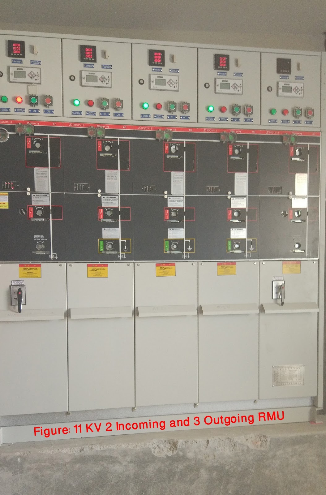
Ring Main Unit (RMU) is a 11 KV or 33 KV HT panel having 3 nos. of switches (Circuit Breakers or Isolators or LBS) that are 2 for incoming one for outgoing. It enables consumer use 2 sources of HT power in at the same metering point. It is a totally sealed, gas-insulated compactswitchgear unit.
RMU is to be used two incoming with mechanical or electrical interlock and one out going to the load generally butsome times one incoming and two outgoings medium voltage supplies. In engineering distribution this is called flexible power supply. Now a day SF6 (Sulfer Hexa-Floride) circuit breakers going to be used. These are maintenance free breakers.
Figure 1 – Outlook of a typical three-feeder 24 kV RMU unit
Figure 2- 11 KV 2 Incoming and 3 Outgoing RMU at Bangladesh Film Archive.
Ring Main Unit is used in a secondary distribution system. It is basically used for an uninterrupted power supply. Alongside, it also protects your secondary side transformer from the occasional transient currents.