Welcome to EEE Interview Tips

For Your Pre-Professional Preparation!

Download EEEBooks

To Download Electrical and Electronics Ebooks click the "EEE Library" menu! Enjoy!!

EEE Interview Tips

Leave Your Comments, Views And Questions.

Learn to make Electronics

Burn things out, mess things up - that's how you learn to Make Electronics! Enjoyy!!

EEE Forum

Drop your Ideas, Thoughts, Questions and Comments!

Showing posts with label Transformer. Show all posts

November 6, 2020

Define the voltage regulation of the transformer. Why it is important?

Voltage Regulation:

The voltage regulation is defined as the change in the magnitude of receiving and sending voltage of the transformer. It is commonly used in power engineering to describe the percentage voltage difference between no load and full load voltages distribution lines, transmission lines, and transformers.


The voltage regulation is represented as:


Importance of Voltage Regulation:

The voltage regulation value provides the efficiency of the transformer & it is best to prefer a transformer with low voltage regulation.

March 11, 2017

Why should Dry-Type Transformers never be overloaded?

Overloading of a transformer results in excessive temperature. This excessive temperature causes overheating which will result in rapid deterioration of the insulation and cause complete failure of the transformer coils.

Can transformers be used in parallel?

 
Figure: Transformers in Parallel


Single phase transformers can be used in parallel only when their impedances and voltages are equal. If unequal voltages are used, a circulating current exists in the closed network between the two transformers, which will cause excess heating and result in a shorter life of the transformer. In addition, impedance values of each transformer must be within 7.5% of each other. For example: Transformer A has an impedance of 4%, transformer B which is to be parallel to A must have an impedance between the limits of 3.7% and 4.3%. When paralleling three phase transformers, the same precautions must be observed as listed above, plus the angular displacement and phasing between the two transformers must be identical.

Can Single Phase Transformers be used for Three Phase applications?

Yes. Three phase transformers are sometimes not readily available, whereas single phase transformers can generally be found in stock. Three single phase transformers can be used in delta connected primary and wye or delta connected secondary. They should never be connected wye primary to wye secondary, since this will result in unstable secondary voltage. The equivalent three phase capacity when properly connected of three single phase transformers is three times the nameplate rating of each single phase transformer. 

For example: Three 10 kVA  single phase transformers will accommodate a 30 kVA three phase load.

What is an Autotransformer? Explain Autotransformer Operation. What are the Limitations, Advantages, Disadvantages and Applications of Autotransformer?

Autotransformer:

An autotransformer (sometimes called autostep down transformer) is an electrical transformer with only one winding. In an autotransformer, portions of the same winding act as both the primary and secondary sides of the transformer. The winding has at least three taps where electrical connections are made. 

On load condition, a part of the load current is obtained directly from the supply and the remaining part is obtained by transformer action. An Auto transformer works as a voltage regulator.

Figure-1: Single-phase tapped autotransformer with an output voltage range of 40%–115% of input.

Operation:

An autotransformer has a single winding with two end terminals, and one or more terminals at intermediate tap points, or it is a transformer in which the primary and secondary coils have part of, or all of their turns in common. The primary voltage is applied across two of the terminals, and the secondary voltage taken from two terminals, almost always having one terminal in common with the primary voltage. The primary and secondary circuits therefore have a number of windings turns in common. Since the volts-per-turn is the same in both windings, each develops a voltage in proportion to its number of turns. In an autotransformer part of the current flows directly from the input to the output, and only part is transferred inductively, allowing a smaller, lighter, cheaper core to be used as well as requiring only a single winding. However the voltage and current ratio of autotransformers can be formulated the same as other two-winding transformers:

One end of the winding is usually connected in common to both the voltage source and the electrical load. The other end of the source and load are connected to taps along the winding. Different taps on the winding correspond to different voltages, measured from the common end. In a step-down transformer the source is usually connected across the entire winding while the load is connected by a tap across only a portion of the winding. In a step-up transformer, conversely, the load is attached across the full winding while the source is connected to a tap across a portion of the winding.

As in a two-winding transformer, the ratio of secondary to primary voltages is equal to the ratio of the number of turns of the winding they connect to. For example, connecting the load between the middle and bottom of the autotransformer will reduce the voltage by 50%. Depending on the application, that portion of the winding used solely in the higher-voltage (lower current) portion may be wound with wire of a smaller gauge, though the entire winding is directly connected.

If one of the center-taps is used for the ground, then the autotransformer can be used as a balun to convert a balanced line (connected to the two end taps) to an unbalanced line (the side with the ground).


Limitations:

An autotransformer does not provide electrical isolation between its windings as an ordinary transformer does; if the neutral side of the input is not at ground voltage, the neutral side of the output will not be either. A failure of the isolation of the windings of an autotransformer can result in full input voltage applied to the output. Also, a break in the part of the winding that is used as both primary and secondary will result in the transformer acting as an inductor in series with the load (which under light load conditions may result in near full input voltage being applied to the output). These are important safety considerations when deciding to use an autotransformer in a given application.

Because it requires both fewer windings and a smaller core, an autotransformer for power applications is typically lighter and less costly than a two-winding transformer, up to a voltage ratio of about 3:1; beyond that range, a two-winding transformer is usually more economical.

In three phase power transmission applications, autotransformers have the limitations of not suppressing harmonic currents and as acting as another source of ground fault currents. A large three-phase autotransformer may have a "buried" delta winding, not connected to the outside of the tank, to absorb some harmonic currents.

In practice, losses mean that both standard transformers and autotransformers are not perfectly reversible; one designed for stepping down a voltage will deliver slightly less voltage than required if it is used to step up. The difference is usually slight enough to allow reversal where the actual voltage level is not critical.

Like multiple-winding transformers, autotransformers use time-varying magnetic fields to transfer power. They require alternating currents to operate properly and will not function on direct current.

Advantages:

  1. An autotransformer requires less Cu than a two-winding transformer of similar rating.
  2. An autotransformer operates at a higher efficiency than a two-winding transformer of similar rating.
  3. An autotransformer has better voltage regulation than a two-winding transformer of the same rating.
  4. An autotransformer has smaller size than a two-winding transformer of the same rating.
  5. An autotransformer requires smaller exciting current than a two-winding transformer of the same rating. 
It may be noted that these advantages of the autotransformer decrease as the ratio of transformation increases. Therefore, an autotransformer has marked advantages only for relatively low values of transformation ratio (i.e. values approaching 1).

Disadvantages:


  1. There is a direct connection between the primary and secondary. Therefore, the output is no longer d.c. isolated from the input.
  2. An autotransformer is not safe for stepping down a high voltage to a low voltage. As an illustration, Figure-2 shows 11000/230 V step-down autotransformer. If an open circuit develops in the common portion 2-3 of the winding, then full-primary voltage (i.e., 11000 V in this case) will appear across the load. In such a case, any one coming in contact with the secondary is subjected to high voltage. This could be dangerous to both the persons and equipment. For this reason, autotransformers are prohibited for general use.
  3. The short-circuit current is much larger than for the two-winding transformer of the same rating. It can be seen from Figure-2 that a short-circuited secondary causes part of the primary also to be short circuited. This reduces the effective resistance and reactance.
Figure-2: 11000/230 V step-down autotransformer.


Applications of Autotransformers:

(i) Power transmission and distribution

Autotransformers are frequently used in power applications to interconnect systems operating at different voltage classes, for example 132 kV to 66 kV for transmission. Another application in industry is to adapt machinery built (for example) for 480 V supplies to operate on a 600 V supply. They are also often used for providing conversions between the two common domestic mains voltage bands in the world (100 V—130 V and 200 V—250 V). The links between the UK 400 kV and 275 kV 'Super Grid' networks are normally three phase autotransformers with taps at the common neutral end.

On long rural power distribution lines, special autotransformers with automatic tap-changing equipment are inserted as voltage regulators, so that customers at the far end of the line receive the same average voltage as those closer to the source. The variable ratio of the autotransformer compensates for the voltage drop along the line.

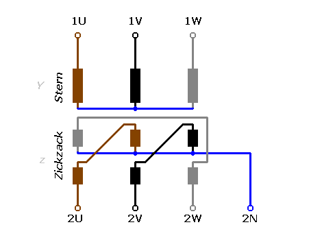
A special form of autotransformer called a zig zag is used to provide grounding on three-phase systems that otherwise have no connection to ground. A zig-zag transformer provides a path for current that is common to all three phases (so-called zero sequence current).

(ii) Audio system

In audio applications, tapped autotransformers are used to adapt speakers to constant-voltage audio distribution systems, and for impedance matching such as between a low-impedance microphone and a high-impedance amplifier input.

(iii) Railways

In UK railway applications, it is common to power the trains at 25 kV AC. To increase the distance between electricity supply Grid feeder points they can be arranged to supply a 25-0-25 kV supply with the third wire (opposite phase) out of reach of the train's overhead collector pantograph. The 0 V point of the supply is connected to the rail while one 25 kV point is connected to the overhead contact wire. At frequent (about 10 km) intervals, an autotransformer links the contact wire to rail and to the second (antiphase) supply conductor. This system increases usable transmission distance, reduces induced interference into external equipment and reduces cost. A variant is occasionally seen where the supply conductor is at a different voltage to the contact wire with the autotransformer ratio modified to suit.

(iv) Autotransformers are used for reducing the voltage supplied to a.c. motors during the starting period.

(v) Autotransformers are used as a voltage regulator.


Download this Article as PDF:
Autotransformer – Operation, Limitations, Advantages, Disadvantages & Applications.

February 18, 2017

What are the purposes of a Transformer?

The purpose of a power transformer in Switch-Mode Power Supplies is to transfer power efficiently and instantaneously from an external electrical source to an external load. In doing so, the transformer also provides important additional capabilities:

  • The primary to secondary turns ratio can be established to efficiently accommodate widely different input/output voltage levels.
  • Multiple secondaries with different numbers of turns can be used to achieve multiple outputs at different voltage levels.
  • Separate primary and secondary windings facilitate high voltage input/output isolation, especially important for safety in off-line applications.

February 15, 2017

If transformers with different electrical characteristics are connected in parallel, what will happen?

They won’t distribute the load equally; one transformer will tend to assume more of the load than the other. This leads to overheating and, in severe cases, the destruction of the transformer(s).

February 10, 2017

What is an Ideal Transformer? State some major differences between an ideal and real transformer.

The Ideal Transformer:

Ideal Transformer is a lossless device with an input winding and an output winding. 
Figure: An ideal transformer.

The major differences between an ideal and real transformer are as follows:

  1. An ideal transformer’s core does not have any hysteresis and eddy current losses.
  2. The magnetization curve of an ideal transformer is similar to a step function and the net mmf is zero.   
  3. Flux in an ideal transformer stays in the core and  hence leakage flux is zero.   
  4. The resistance of windings in an ideal transformer is zero.

January 15, 2017

What is RMU (Ring Main Unit) and Its Use in Electrical Power Distribution System?

Ring Main Unit (RMU) is a 11 KV or 33 KV HT panel having 3 nos. of switches (Circuit Breakers or Isolators or LBS) that are 2 for incoming one for outgoing. It enables consumer use 2 sources of HT power in at the same metering point. It is a totally sealed, gas-insulated compact switchgear unit.

RMU is to be used two incoming with mechanical or electrical interlock and one out going  to the load generally but some times one incoming and two outgoings medium voltage supplies. In engineering distribution this is called flexible power supply. Now a day SF6 (Sulfer Hexa-Floride) circuit breakers going to be used. These are maintenance free breakers. 


Figure 1 – Outlook of a typical three-feeder 24 kV RMU unit

Figure 2- 11 KV 2 Incoming and 3 Outgoing RMU at Bangladesh Film Archive.

Ring Main Unit is used in a secondary distribution system. It is basically used for an uninterrupted power supply. Alongside, it also protects your secondary side transformer from the occasional transient currents. 

October 31, 2016

If transformers with different electrical characteristics are connected in parallel, what will happen?

They won’t distribute the load equally; one transformer will tend to assume more of the load than the other. This leads to overheating and, in severe cases, the destruction of the transformer(s).

What is an induction regulator?

This device is similar to a booster transformer. It has a primary and a secondary winding, which are wound on separate cores. The primary can be moved in either direction; this is usually done by an electric motor. In turning, the primary bucks or boosts the line voltage, as required. The amount of bucking or boosting is anticipated by the current being drawn by the line.

What is the relationship between the current and voltage in the high side of a transformer and the current and voltage in the low side of a transformer? Draw a diagram showing this relationship.

With respect to the turns ratio, the current in one side of a transformer is inversely proportional to the current in the other side, whereas the voltage across one side of a transformer is directly proportional to the voltage across the other side. These are illustrated in Figure-1.

September 18, 2016

12 Most Common Interview Questions and Answers on Transformer - Part 2

Q. 1: What is induction?

A. 1: The process by which one conductor produces, or induces, a voltage in another conductor, even though there is no mechanical coupling between the two conductors.

Q. 2: What is inductance?

A. 2: The property of a coil in a circuit to oppose any change of existing current flow.


Q. 3: What is self-inductance?

A. 3: The inducing of an emf within the circuit itself, caused by any change of current within that circuit. This induced emf is always in a direction opposite to the applied emf, thus causing opposition to any change in current within the circuit itself.

Q. 4: What is mutual inductance?

A. 4: The linkage of flux between two coils or conductors, caused by the current flowing within one or both of the coils or conductors.

Q. 5: Name several methods by which an emf can be generated.

A. 5: By conductors being cut by-
  • A magnetic field (as in generators) 
  • Chemical reactions (as in batteries)
  • Heat (as in thermocouples)
  • Crystal vibration (as in piezoelectricity) and 
  • Friction (as in static electricity).


Q. 6: What is a transformer?

A. 6: A device that transforms electrical energy from one or more circuits to one or more other circuits at the same frequency but usually at a different voltage and current. It consists of a core of soft-iron laminations surrounded by coils of copper-insulated wire.

Q. 7: Draw a diagram of two coils, such as the coils of a transformer winding, and indicate the self-inductance and the mutual inductance.

A. 7: Self-inductance is produced within the primary coil, and mutual inductance exists between the two transformer coils, as shown bellow this Figure:
Self-inductance and mutual inductance in the coils of a Transformer.
Figure: Self-inductance and mutual inductance in the coils of a Transformer.

Q. 8: What always surrounds a conductor when a current flows through it?

A. 8: A magnetic field.

Q. 9: There are two basic types of transformers. What are they?

A. 9: The isolation type, in which the two windings are physically isolated and electrically insulated from each other, and the autotransformer type, in which there is only one coil with a tap or taps taken off it to secure other voltages (the primary is part of the secondary and the secondary is part of the primary).


Q. 10: What is an oil-immersed transformer?

A. 10: The core and coils are immersed in a high-grade mineral oil, which has high dielectric qualities.

Q. 11: What is Transformer Oil?

A. 11: Transformer oil or insulating oil is an oil that is stable at high temperatures and has excellent electrical insulating properties. It is used in oil-filled transformers, some types of high-voltage capacitors, fluorescent lamp ballasts, and some types of high-voltage switches and circuit breakers. Its functions are to insulate, suppress corona and arcing, and to serve as a coolant.

Transformer oil is most often based on mineral oil, but alternative formulations with better engineering and/or environmental properties are growing in popularity.

Q. 12:  Why is oil used in a transformer?

A.12: To increase the dielectric strength of the insulation, to keep down the possibility of arcing between coils, and to dissipate heat to the outer case so that the transformer can carry heavier loads without excessive overheating.

Courtesy: 
  1. Book of Paul Rosenberg
  2. Wikipedia
  3. Internet.
Download this Article as PDF:
 12-most-common-interview-question-and answers on transformer

September 12, 2016

Discuss about different types of Transformers and their Applications.

Transformer:


A transformer is an electrical device that transfers electrical energy between two or more circuits through electromagnetic induction. Electromagnetic induction produces an electromotive force across a conductor which is exposed to time varying magnetic fields. Commonly, transformers are used to increase or decrease the voltages of alternating current in electric power applications.


Photo: Dry type Transformer

Types of Transformers:

1.        Power transformers

a)         Laminated core transformer
b)         Toroidal transformer
c)         Autotransformer
d)         Variable autotransformer
e)         Induction regulator transformer
f)          Polyphase transformer
g)         Grounding transformer
h)         Leakage or stray field transformers
i)          Resonant transformer
j)          Constant voltage transformer
k)         Ferrite core transformer
l)          Planar transformer
m)        Oil cooled transformer
n)         Cast resin transformer
o)         Isolating transformer

2.     Instrument transformer

a)         Current transformer
b)         Voltage transformer or potential transformer
c)         Combined instrument transformer

3.      Pulse transformer

4.      RF transformer

a)         Air-core transformer
b)         Ferrite-core transformer
c)         Transmission-line transformer
d)         Balun transformer

5.     Audio transformer

a)         Loudspeaker transformer
b)         Output transformer
c)         Small signal transformer
d)         Interstage and coupling transformers

6.     Other types

a)         Hedgehog
b)         Variometer and variocoupler
c)         Rotary transformer


Overview and Applications of Transformers:

1. Auto-transformer

An auto-transformer has only a single winding with two end terminals, plus a third of an intermediate tap point. The primary voltage is applied across two of the terminals, and the secondary voltage taken from one of these and the third terminal. The primary and secondary circuits therefore have a number of windings turns in common. An adjustable auto-transformer is made by the secondary connection through a sliding brush, giving a variable turns ratio.
Figure: Single-phase tapped autotransformer with output voltage range of 40%–115% of input

Applications: 

  • Large three-phase autotransformers are used in electric power distribution systems, for example, to interconnect 33 kV and 66 kV sub-transmission networks.

2. Polyphase transformers

For three-phase power, three separate single-phase transformers can be used, or all three phases can be connected to a single polyphase transformer. In this case, the magnetic circuits are connected together, the core, thus containing a three-phase flow of flux. The three primary windings are connected together and the three secondary windings are connected together. The most common connections are Y-∆, ∆-Y, ∆-∆ and Y-Y. If a winding is connected to earth (grounded), the earth connection point is usually at the center point of a Y winding.

Applications:

  • For higher- power applications, poly-phase transformers are commonly used. 


3. Leakage transformers

A leakage transformer, also called a stray-field transformer, has a significantly higher leakage inductance than other transformers, sometimes increased by a magnetic bypass or shunt in its core between primary and secondary, which is sometimes adjusted with a set screw. This provides a transformer with an inherent current limitation due to the loose coupling between its primary and the secondary windings. The output and input currents are low enough to prevent thermal overload under all load conditions – even if the secondary is shorted. 
Figure: Leakage Transformer or Stray field Transformer.

Applications: 

  • Leakage transformers are used for arc welding and high voltage discharge lamps. 
  • Other applications are short-circuit-proof extra-low voltage transformers for toys or doorbell installations.


4. Resonant transformers

A resonant transformer is a kind of the leakage transformer. It uses the leakage inductance of its secondary windings in combination with external capacitors, to create one or more resonant circuits. Resonant transformers such as the Tesla coil can generate very high voltages, and are able to provide much higher current than electrostatic high-voltage generation machines such as the Van de Graaff generator. 

Applications: 

  • Intermediate frequency (IF) transformer in superheterodyne radio receiver
  • Tank transformers in radio transmitters
  • Tesla coil
  • Oudin coil (or Oudin resonator; named after its inventor Paul Oudin)
  • D'Arsonval apparatus
  • Ignition coil or induction coil used in the ignition system of a petrol engine
  • Electrical breakdown and insulation testing of high voltage equipment and cables. In the latter case, the transformer's secondary is resonated with the cable's capacitance.

5. Instrument transformers

A current transformer is a measurement device designed to provide a current in its secondary coil proportional to the current flowing in its primary. Current transformers are commonly used in metering and protective relaying, where they facilitate the safe measurement of large currents. The current transformer isolates measurement and control circuitry from the high voltages typically present on the circuit being measured. Voltage transformers (VTs)--also referred to as potential transformers (PTs)--are used for metering and protection in high-voltage circuits. They are designed to present negligible load to the supply being measured and to have a precise voltage ratio to accurately step down high voltages so that metering and protective relay equipment can be operated at a lower potential.


Figure: Current transformers used in metering equipment for three-phase 400 ampere electricity supply

Applications: 

  • Used as a portable current measuring instrument.
  • Measurement of high voltages is possible by the potential transformers.


6. Zigzag transformer

A zigzag transformer is a special purpose transformer. It has primary windings but no secondary winding. Its applications are for the creation of a missing neutral connection from an ungrounded 3-phase system to permit the grounding of that neutral to an earth reference point and also harmonic mitigation, as it can suppress triplet (3rd, 9th, 15th, 21st, etc.) harmonic currents, to supply 3-phase power as an autotransformer (serving as the primary and secondary with no isolated circuits)  and to supply non-standard, phase-shifted, 3-phase power.


Figure: Zigzag transformer

Applications: 

  • One application is to derive an earth reference point for an ungrounded electrical system. 
  • Another is to control harmonic currents.

7. Pulse transformers

A pulse transformer is a transformer that is optimized for transmitting rectangular electrical pulses (that is, pulses with fast rise and fall times and constant amplitude). 


Figure: Bothhand TS6121A pulse transformer

Applications:

  • Small versions called signal types are used in digital logic and telecommunications circuits, often for matching logic drivers to transmission lines. 
  • Medium-sized power versions are used in power-control circuits such as camera flash controllers. 
  • Larger power versions are used in the electrical power distribution industry to interface low-voltage control circuitry to the high-voltage gates of power semiconductors. 
  • Special high voltage pulse transformers are also used to generate high power pulses for radar, particle accelerators, or other high energy pulsed power applications.

8. Audio transformer

Audio transformers or Audio Frequency (AF) Transformers are those specifically designed for use in audio circuits to carry audio signal. They can be used to block radio frequency interference or the DC component of an audio signal, to split or combine audio signals, or to provide impedance matching between high and low impedance circuits, such as between a high impedance tube (valve) amplifier output and a low impedance loudspeaker, or between a high impedance instrument output and the low impedance input of a mixing console. Audio transformers that operate with loudspeaker voltages and current are larger than those that operate at microphone or line level, which carry much less power.


Figure: Audio Frequency (AF) Transformers

Application: 

  • Audio transformers are used in car radios and broadcast equipment, and in sound reinforcement applications to steps up the output of the system's amplifier.


9. Isolation transformers 

An isolation transformer is a device that transfers energy from the alternating current (AC) supply to an electrical or electronic load.  It isolates the windings to prevent transmitting certain types of harmonics. 


Figure: A 230V isolation transformer.

Applications: 

  • It is used as a power supply for medical equipment, when it is necessary to prevent any leakage from the AC power system into devices connected to a patient.
  • Some small transformers are used for isolation in pulse circuits.
  • In electronics testing and servicing an isolation transformer is a 1:1 (under load) power transformer used for safety.
  • Supplying power to ships.

10. Buck boost transformers

A Buck boost transformer is a type of transformer used to make adjustments to the voltage applied to alternating current equipment. Buck boost transformers make small adjustments to the incoming voltage. One major advantages of Buck boost transformers are their low cost, compact size and light weight. 
Figure: Typical multi-tap buck–boost transformer.

Applications:

  • Buck boost transformers can be used to power low voltage circuits including control, lighting circuits, or applications that require 12, 16, 24, 32 or 48 volts, consistent with the design's secondaries.
  • They are often used to change voltage from 208v to 240v for lighting applications. 

11. Pad mounted transformers 

A padmount or pad-mounted transformer is a ground mounted electric power distribution transformer in a locked steel cabinet mounted on a concrete pad. Since all energized connection points are securely enclosed in a grounded metal housing, a padmount transformer can be installed in places that do not have room for a fenced enclosure. Padmount transformers are used with underground electric power distribution lines at service drops, to step down the primary voltage on the line to the lower secondary voltage supplied to utility customers. A single transformer may serve one large building, or many homes. Pad Mounted Transformers are usually single phase or three phase and is used where safety is a main concern.


Figure: Large pad-mount transformers supplying power to a computer data center. No live wires are exposed.

Applications:

  • Typical Application is restaurant, commercial building, shopping mall, institutional. 


12. Pole mounted transformers 

Outside a typical house one can see one of these devices mounted on the top of an electrical pole.
Figure: Pole mounted distribution transformer.

Applications:

  • Pole Mounted Transformers are used for distribution in areas with overhead primary lines. 


13. Oil filled transformers 

Oil-filled transformers are transformers that use insulating oil as insulating materials.  The oil helps cool the transformer. Because it also provides part of the electrical insulation between internal live parts, transformer oil must remain stable at high temperatures over an extended period.

Applications: 

  • Oil filled transformers are used in power distribution or electrical substations.


14. Rotary transformers

A rotary (rotatory) transformer is a specialized transformer used to couple electrical signals between two parts that rotate in relation to each other. They may be either cylindrical or 'pancake' shaped.


Figure: Cross-section diagram of a simple rotary transformer.

Applications: 

  • Rotary transformers are most commonly used in videocassette recorders. 
  • Another use is to transmit the signals from rotary torque sensors installed on electric motors, to allow electronic control of motor speed and torque using feedback.

15. Dry type transformers 

Dry type transformers require minimum maintenance to provide many years of reliable trouble free service. Unlike liquid fill transformers which are cooled with oil or fire resistant liquid dielectric, dry type units utilize only environmentally safe, CSA and UL recognized high temperature insulation systems. Dry type transformers provide a safe and reliable power source which does not require fire proof vaults, catch basins or the venting of toxic gasses. These important safety factors allow the installation of dry type transformers inside buildings close to the load, which improves overall system regulation and reduces costly secondary line losses. 

Dry type transformers are a rather mature product and technology, but of all the components in a power system, a transformer replacement can be a physically challenging event, extended delivery of a replacement or repair unit and expensive transportation costs. These are transformers whose core and coils are not immersed in insulating oil. 

“Dry type” simply means it is cooled by normal air ventilation. The dry type transformer does not require a liquid such as oil or silicone or any other liquid to cool the electrical core and coils

Applications:

  • Fire-resistant dry type or "cast resin" transformers are well suited for installation in high rise buildingshospitalsunderground tunnelsschoolsteel factories, chemical plants and places where fire safety is a great concern. Hazard free to the environment, dry type transformers have over the years proven to be highly reliable. 

Download this Article as PDF:
 Different Types Of Transformers And Their Applications

Related Posts Plugin for WordPress, Blogger...